Open Duco With Open Air
Introduction
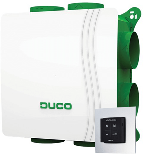
Humans, as a species, have gotten so good at creating nice looking and well isolated caves that we have to now install house ventilation so that we don’t suffocate because we refuse to go outside. Luckily, capitalism has us covered with pre-engineered solutions such as the one present in my own home, the DucoBox Silent:
 .
.
This handy-dandy device will automatically recycle the air in my house and offers a nifty remote control to manually adjust its settings when you try that “how-hard-can-it-be” cooking tutorial on YouTube and end up with a smoke-filled kitchen. It can even be expanded with convvenient sensors to automatically adjust its settings based on the humidity and CO2 levels in the house.
..but what if I want more control? Surely the protocols used by this device are open and documented so that I can integrate it with my home automation system? Well, no. The DucoBox Silent uses a proprietary protocol to communicate with its remote control and sensors.
The solution
Luckily for us, GitHub user Flamingo-Tech has created a solution, the Open AIR. An open-source, drop-in replacement PCB for ventilation systems like the Duco. Even the sensors are offered as open-source hardware. Neat :). Let’s play with it.
Flashing the hardware
Now, if you’re feeling adventurous, you can order the PCBs and components and solder them yourself. I’m not, so I just odered the pre-assembled PCB’s.
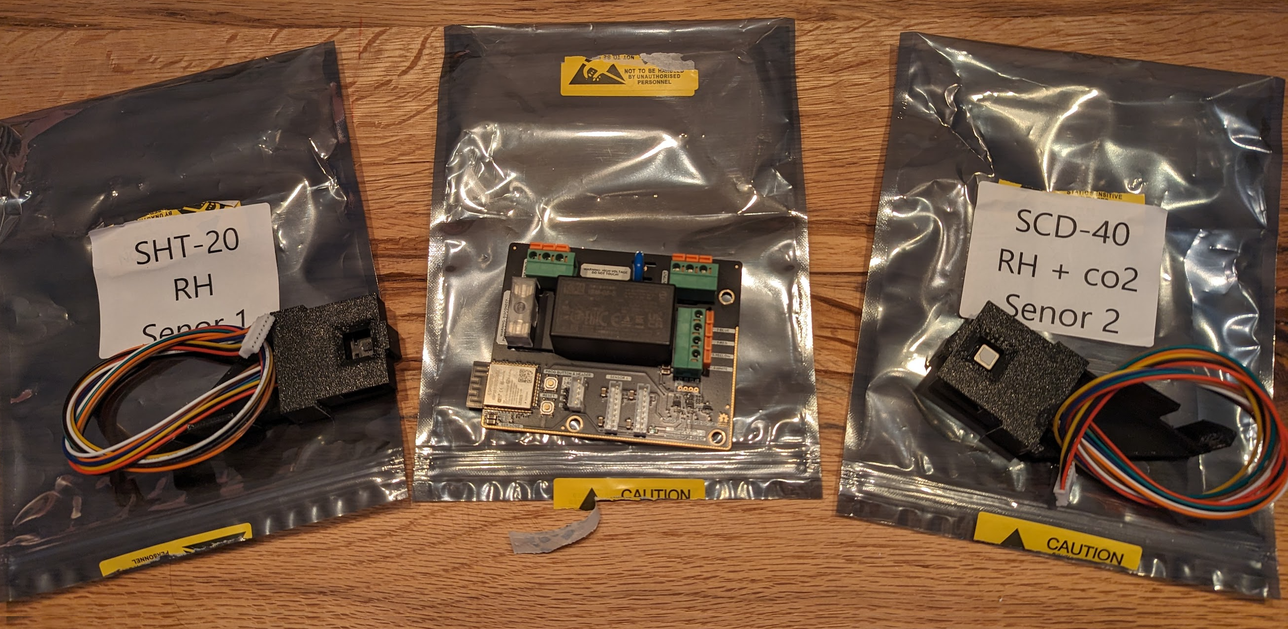
There they are! The Open AIR board in the middle, flanked by the two sensors (or, Señors. Olé!). It might just be my love of everything matte black, but I think the Open AIR looks awesome. Now, typically, the board will come without any software on it so you’ll have to flash it yourself. If you’re uncomfortable with this you can have it pre-flashed for a small fee. If that is what you did, you can skip down to Installation.
For me, flashing is part of the fun! So let’s get to it. We will be flashing it using ESPHome. Their website offers a comprehensive guide on how to connect the actual hardware. In this case we’ll be using a cheap USB Serial Adapter.
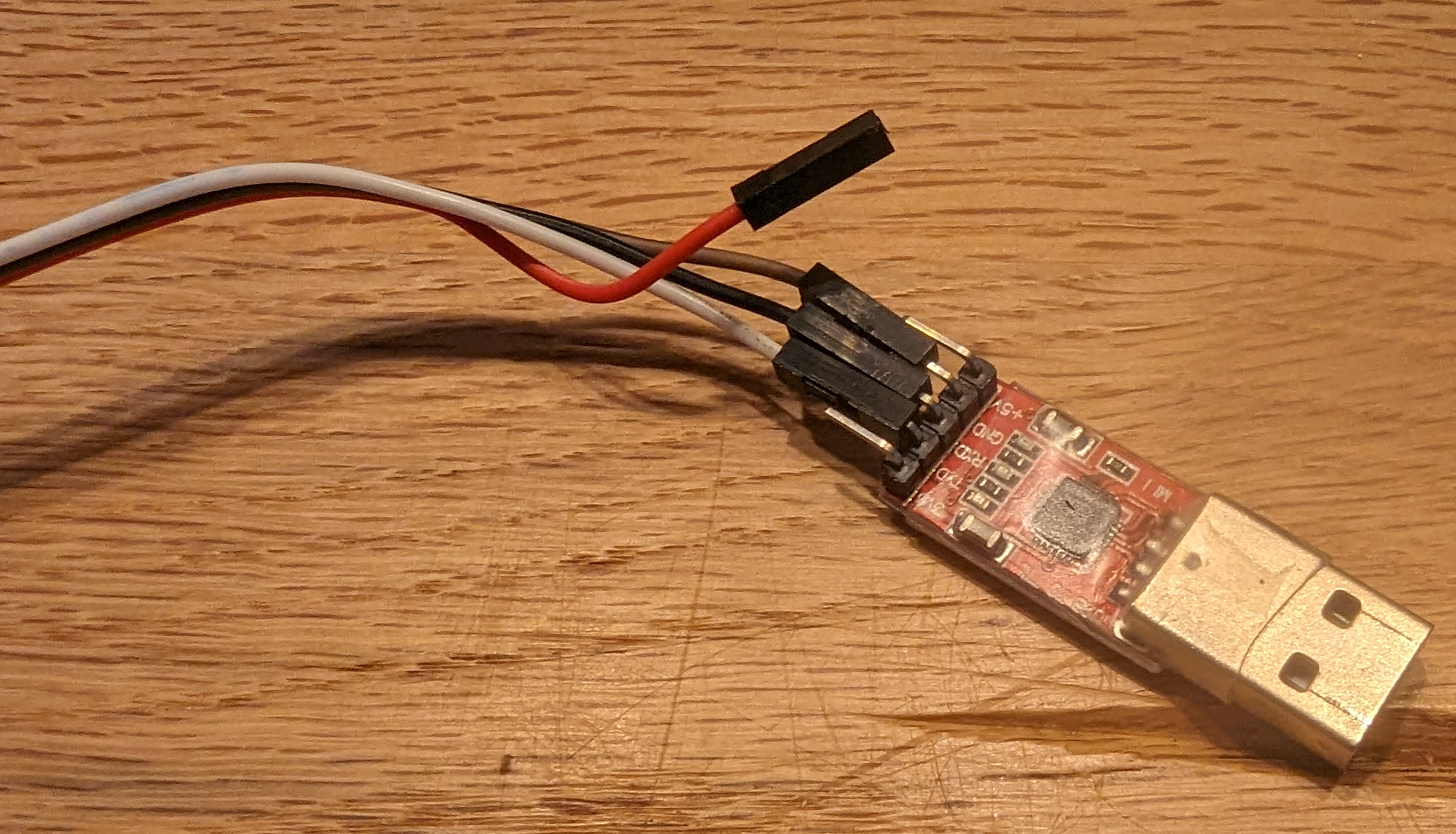
Simply connect the wires as follows:
| USB Serial Adapter | Open AIR |
|---|---|
| GND | GND |
| TX | RX |
| RX | TX |
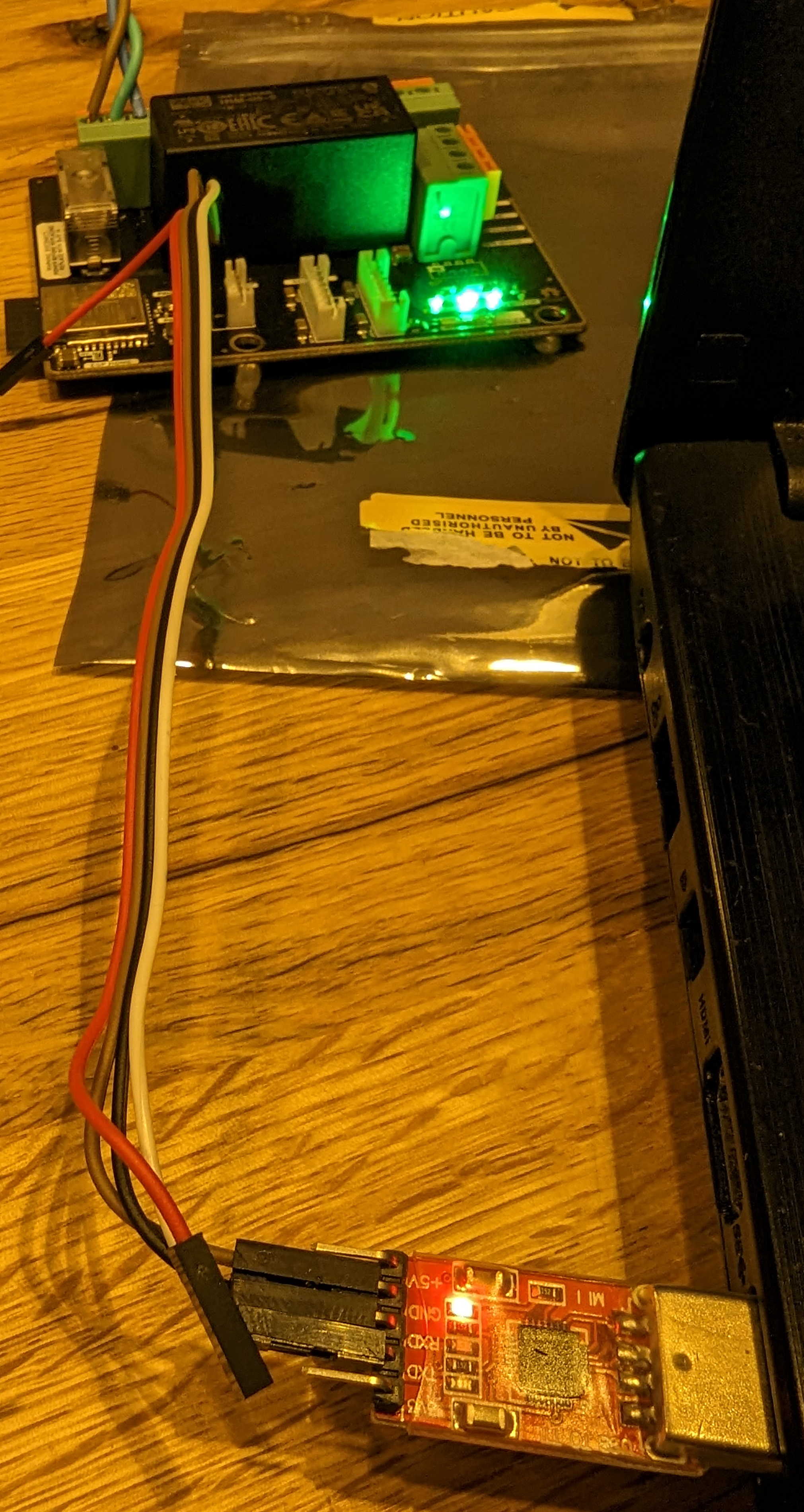
Don’t forget to also connect some power. I just used an old power cord and cut off the end. The end result should be something like this:
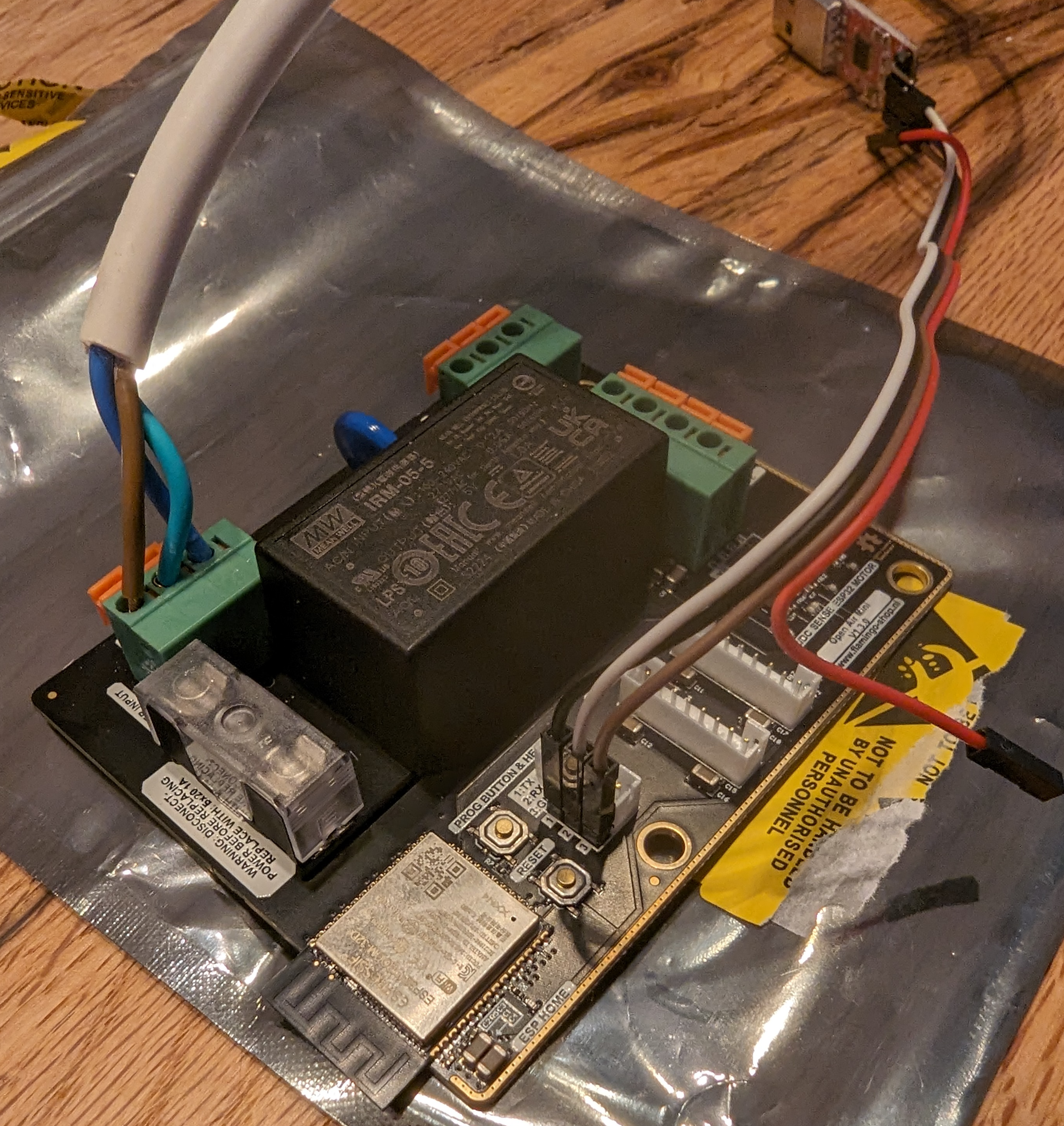
Plug in the USB Serial Adapter, and power on the Open AIR board:
Open a browser that supports the Web Serial API (I used Chrome) and navigate to the ESPHome dashboard. I personally use the ESPHome Add-On for Home Assistant, but there are other options listed under the “Getting started” header on their website.
As you can see, I already have a few devices configured:
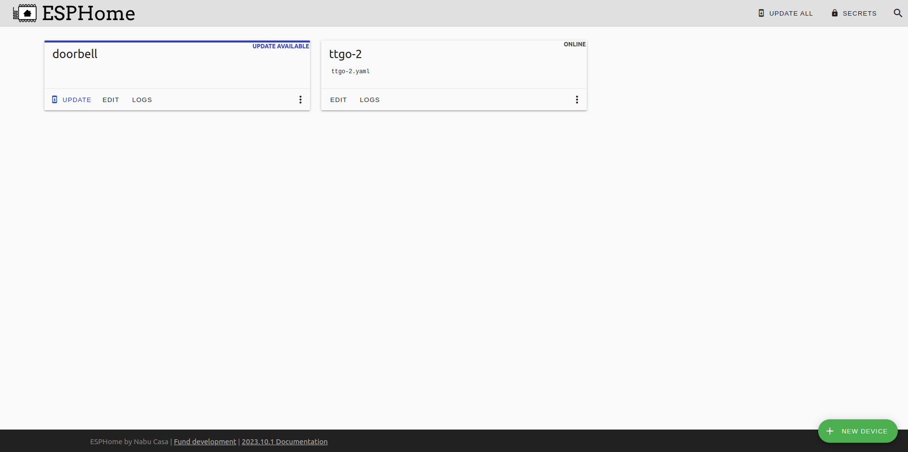
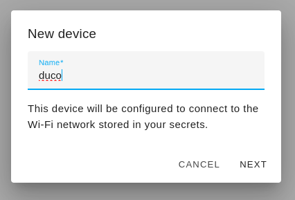
Here, we click “New Device” and give it a name:
In the next window, click connect:
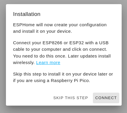
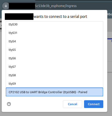
A window in your browser should pop up asking for what device to use. Select the USB Serial Adapter and click connect:
ESPHome will now try to connect to the device:
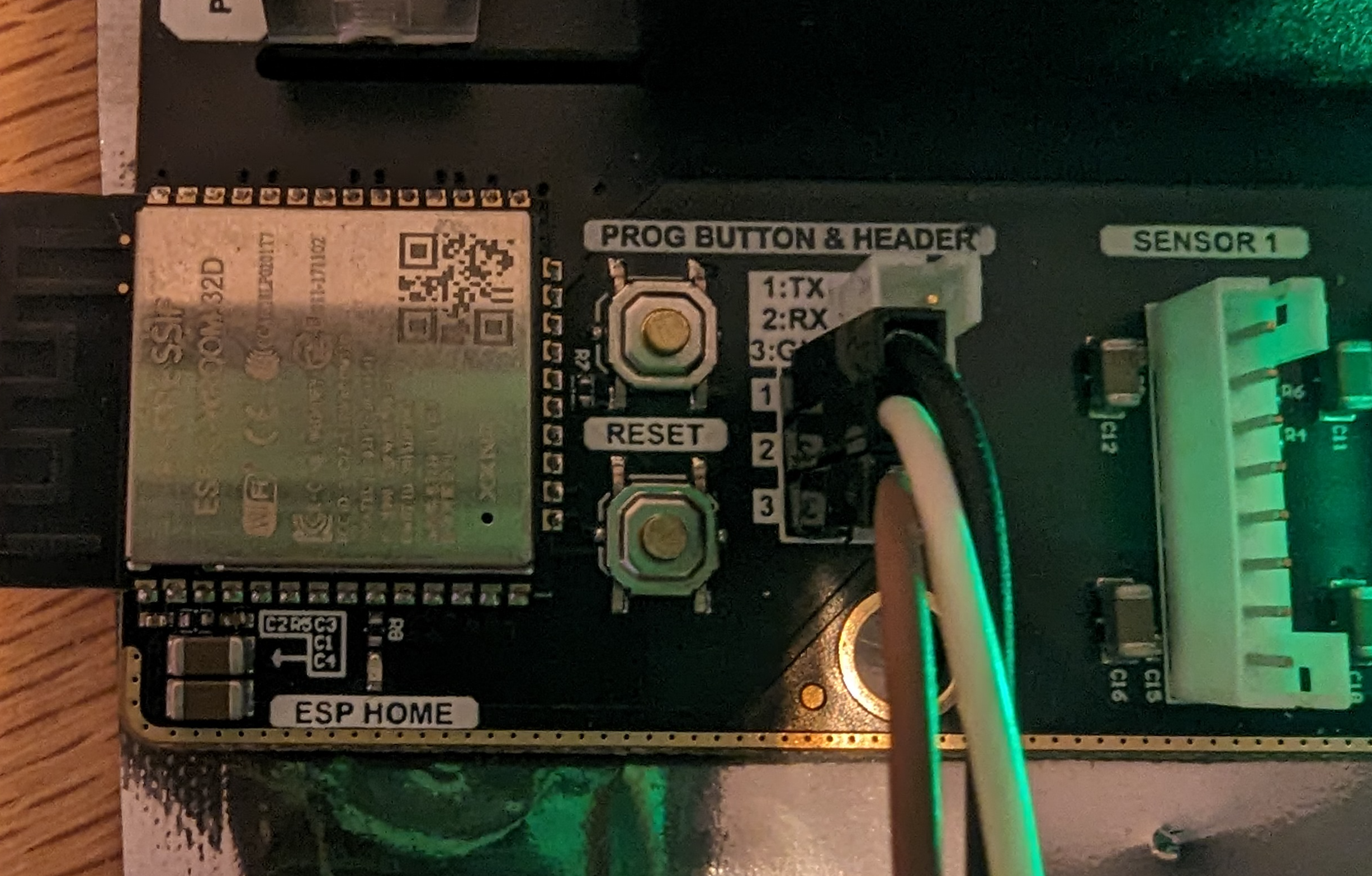
While this is happening, hold the prog button and press the reset button on the Open AIR board:
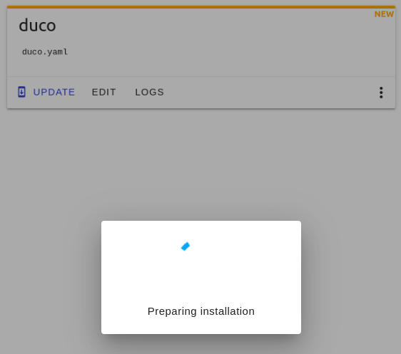
From here, you should see the device connect and ESPHome do its thing. If you’re having trouble, check the ESPHome documentation for more information:
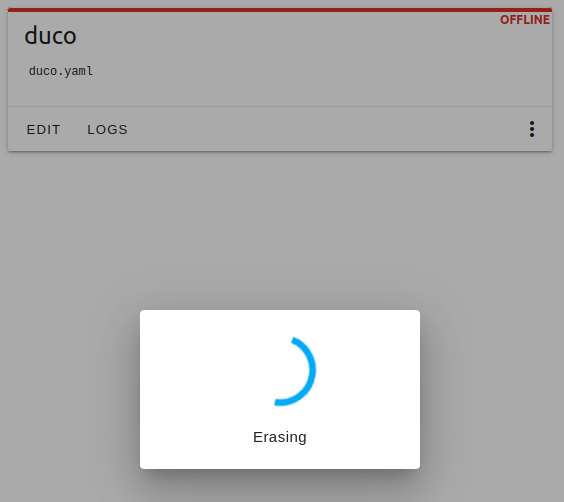
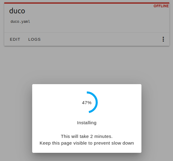
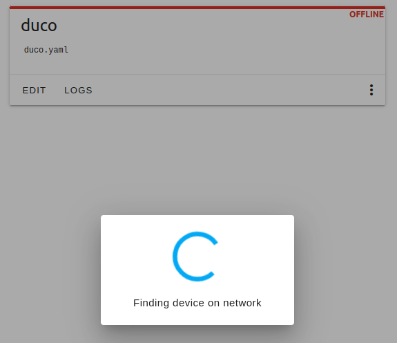
At this point you should push the reset button on the Open AIR board again to reboot it. If you were fast enough you’ll see:
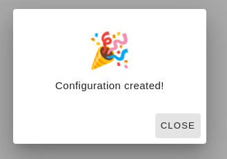
If you weren’t fast enough, ESPHome will tell you it created a configuration but did not find the device on the network. This is fine. In either case, click the LOGS button for the device you just added and you should see something like this:
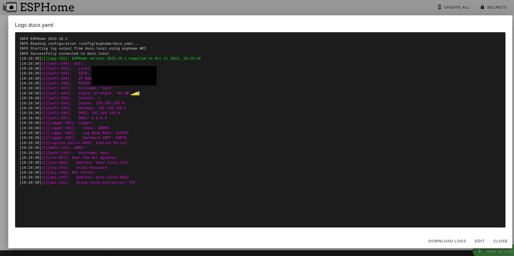
Congratulations! You’ve succesfully flashed the Open AIR board and flashed it with ESPHome! Now, let’s install and configure it.
Installation
So, at this point it’s time to get the screwdriver out. But before you begin: UNPLUG THE POWER. Then, carry on. Here is our willing victim volunteer:
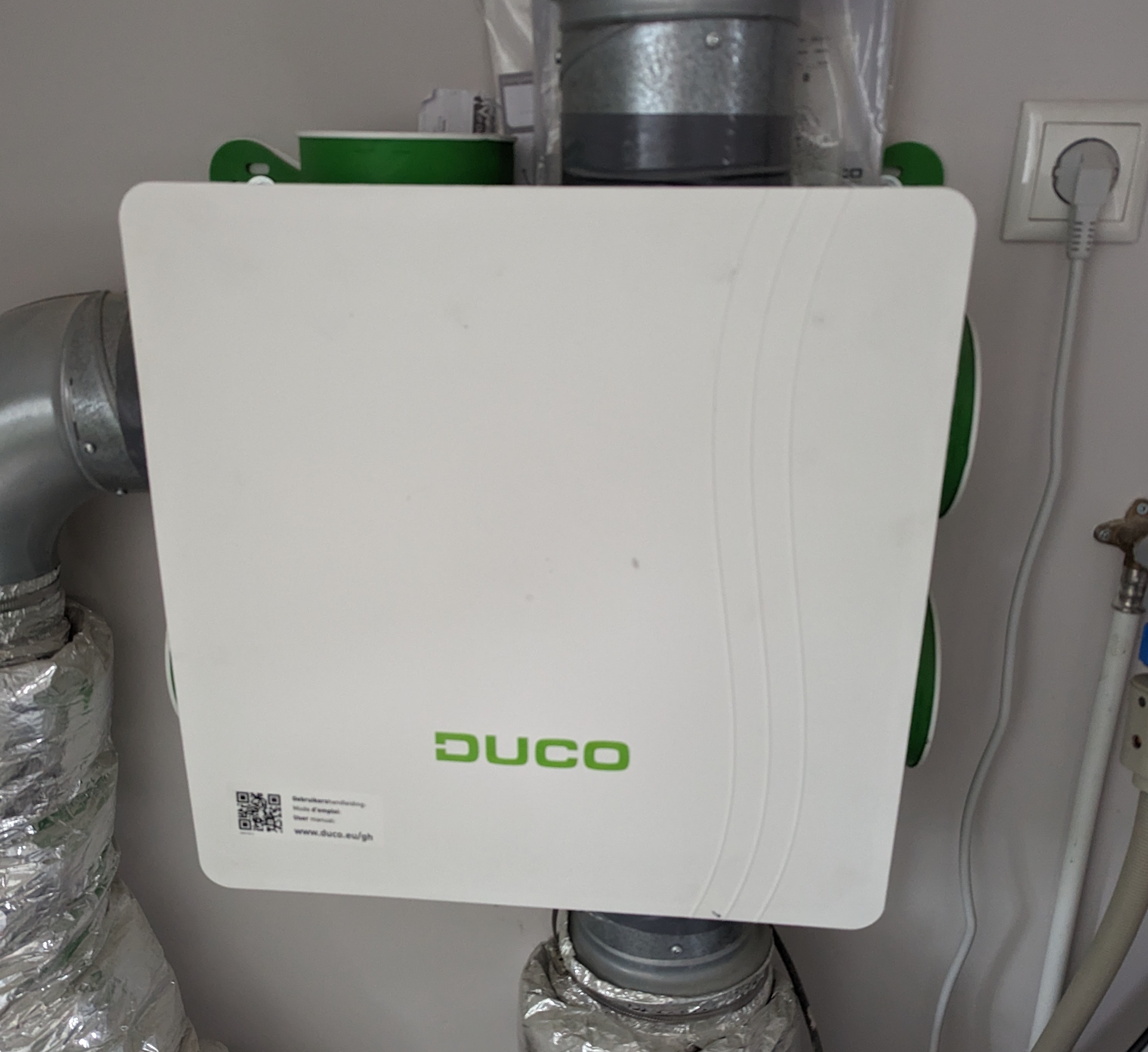
The white cover just pops off when you pull the corners, revealing a rather simple setup:
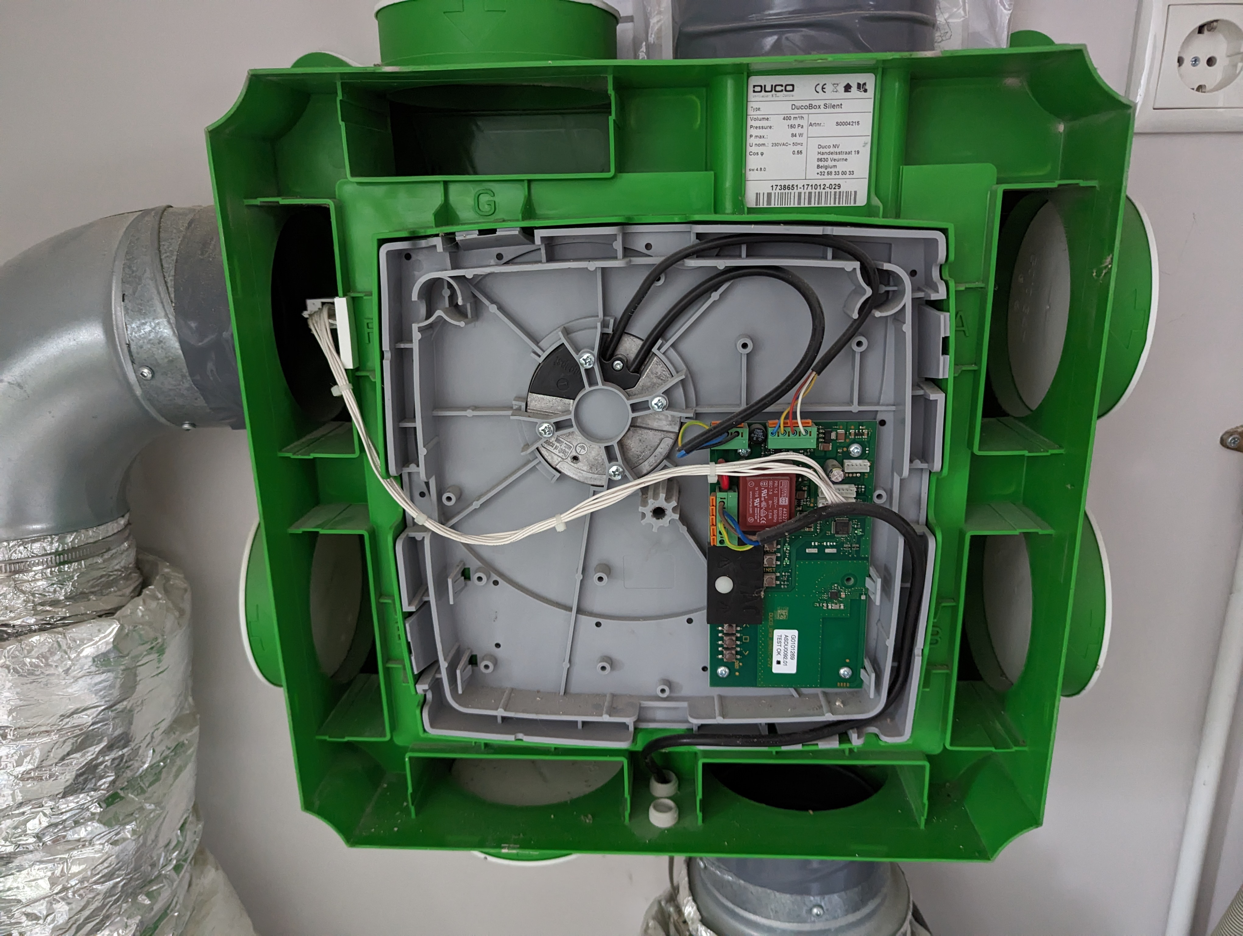
The Open AIR board will replace the existing PCB. It’s a simple swap. Just remove the old PCB and put the Open AIR in its place. A simple matter of loosening the four screws and removing the wiring. Then, do the reverse with the new board. Note that it does sit a bit higher than the old board and uses different screw holes.
Since I also have two new sensors, I will also be replacing the old (white) humidity sensor with the Open AIR version:
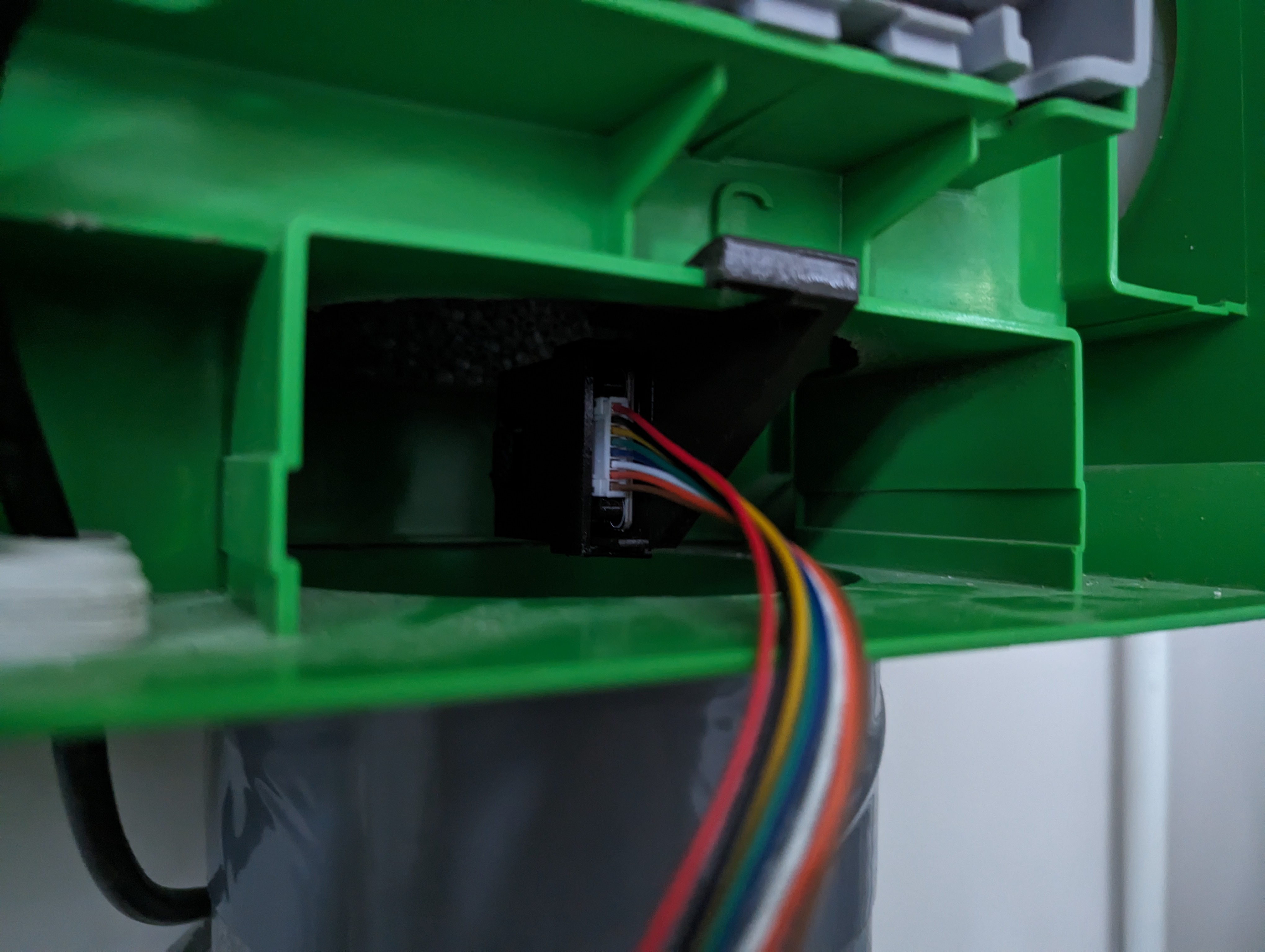
And this is everything completely installed:
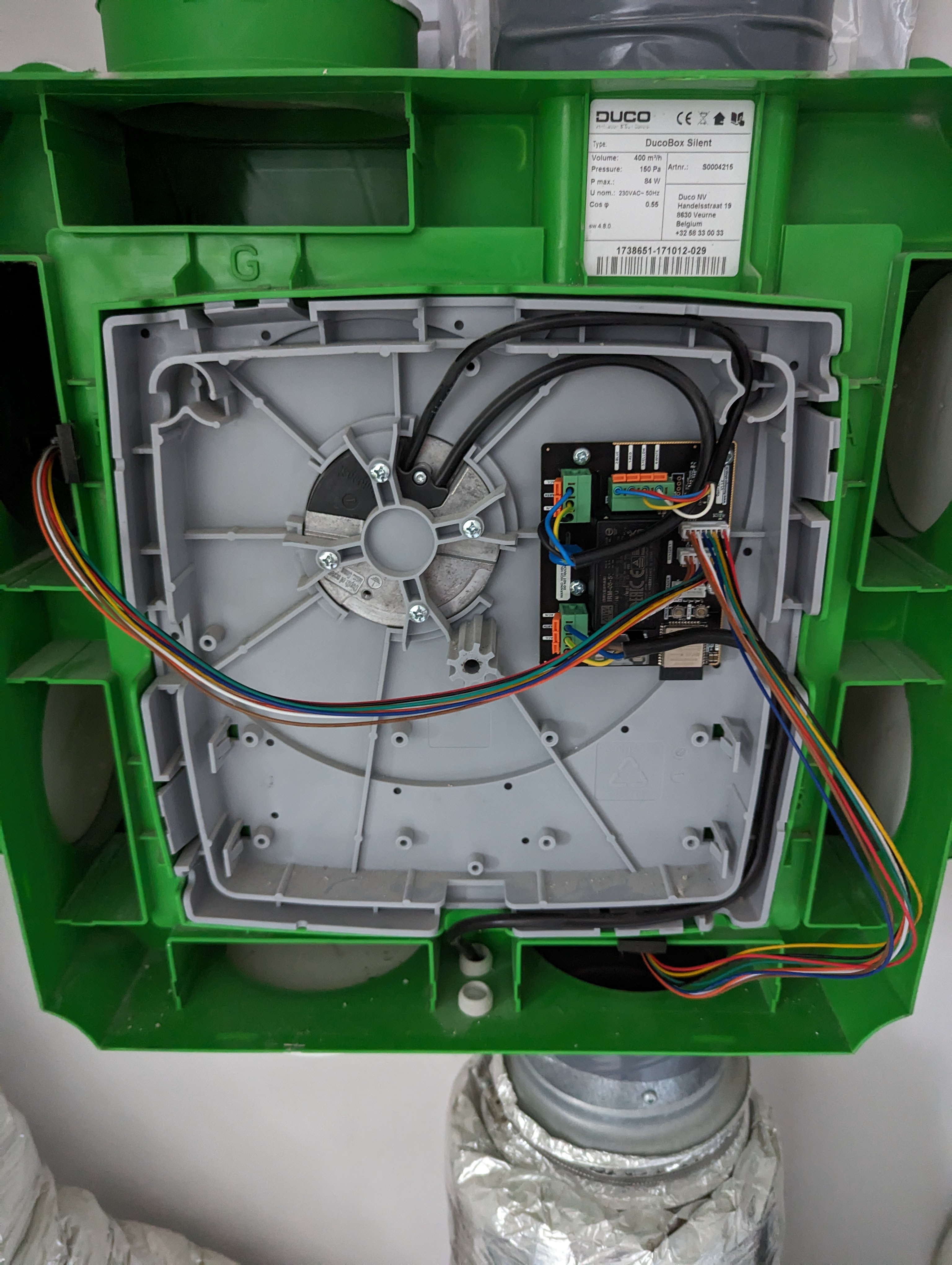
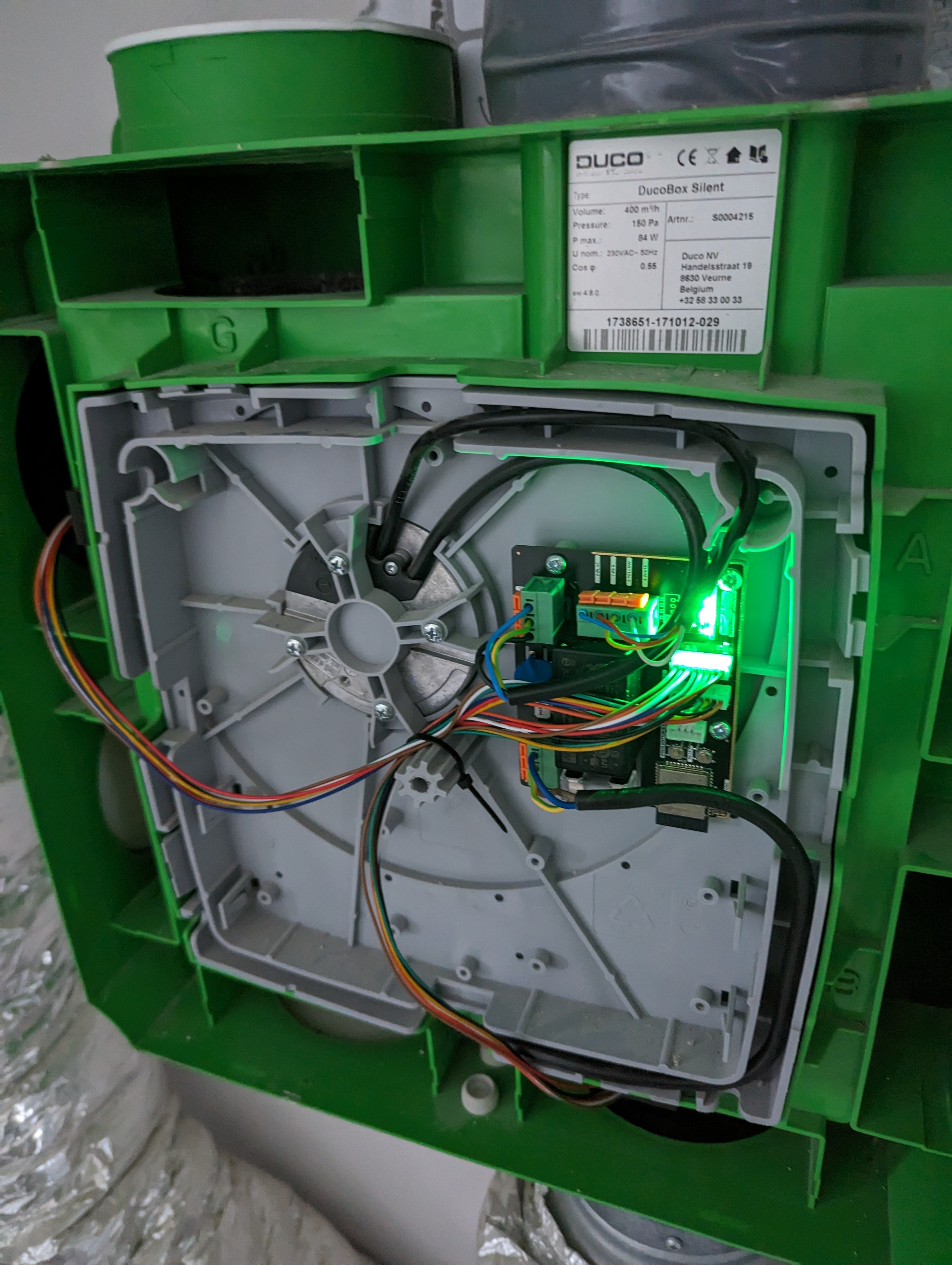
Doing some cable management and plugging in the power you should be greeted by some green LEDs:
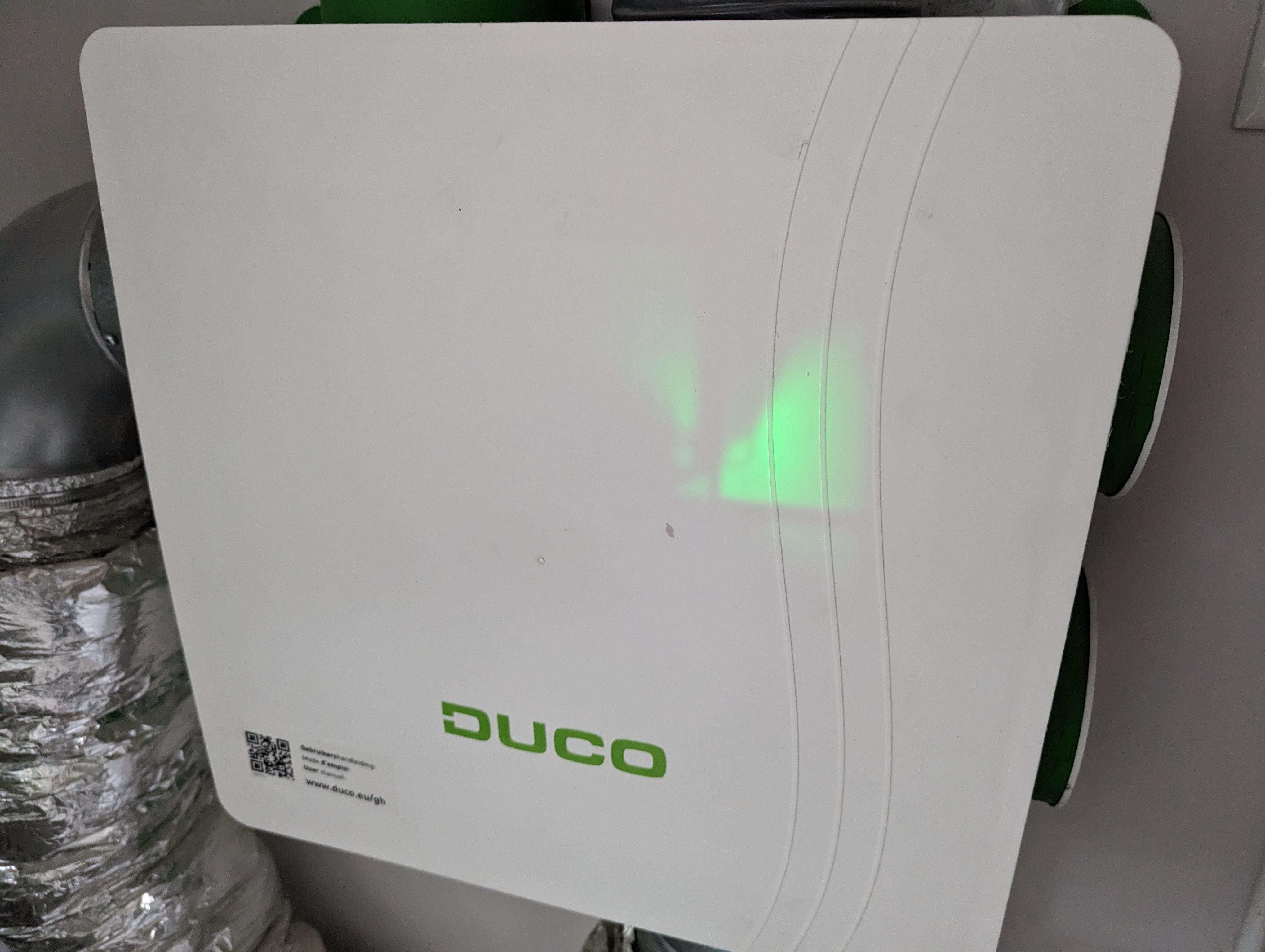
Put the cover back on with some mild violence and you’re done (including cool ominous glow):
Adding to Home Assistant
If you’ve bought the board pre-flashed, you should see a WiFi network pop up after powering on the device. This is the ESPHome captive portal. Use this to connect the device to your own WiFi network. The WiFi information for the captive portal should be:
SSID: Open-AIR-Mini FallbackPassword: ChangeMe@123!
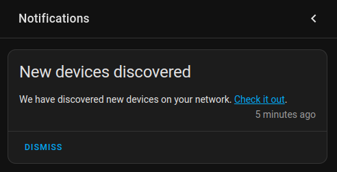
Once it has connected to WiFi Home Assistant should already detect it and give you a notification:
If not it should also show up on the Devices page:
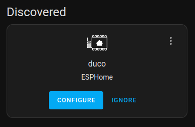
Click CONFIGURE and follow the steps to add it. Then, open up your ESPHome dashboard to continue configuring the device.
Configuration
If you click on the EDIT button, you’ll see that ESPHome generated a basic configuration for us (don’t worry, I’ve changed the passwords):
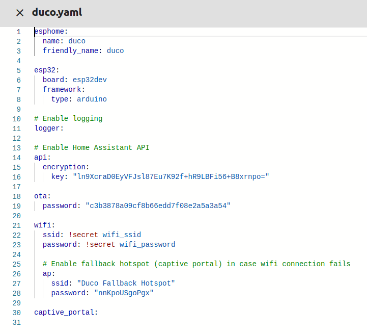
This is enough to get the Open AIR connected, but doesn’t expose any sensors or functionality yet. So let’s build that out. Here is the base configuration:
esphome:
  name: duco
  friendly_name: duco

esp32:
  board: esp32dev
  framework:
    type: arduino

# Enable logging
logger:

# Enable Home Assistant API
api:
  encryption:
    key: "<your-encryption-key>"

ota:
  password: "<your-password>"

wifi:
  ssid: !secret wifi_ssid
  password: !secret wifi_password

  # Enable fallback hotspot (captive portal) in case wifi connection fails
  ap:
    ssid: "Duco Fallback Hotspot"
    password: "<your-hotspot-password>"

captive_portal:
Now, most of this is documented in the Open Air software README, but I like to always start with a minimal configuration and work my way up. Let’s start with the status LED. Add the following to the configuration:
status_led:
  pin:
    number: GPIO33
Next step, add control and readout of the fan. Add a Sensor Component and a Pulse Counter sensor:
sensor:
  - name: "Fan RPM"
    platform: pulse_counter
    pin: GPIO14
    unit_of_measurement: "rpm"
    accuracy_decimals: 0
Now do a small test to see if it works by installing the new configuration. Click INSTALL in the top right and select Wirelessly:
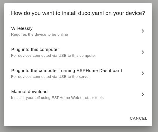
You should see something similar to this:
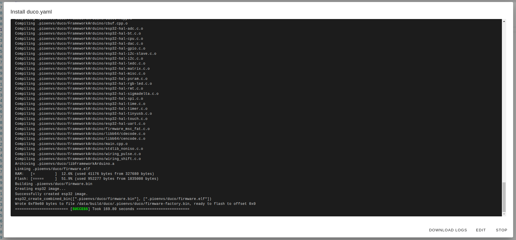
Finally, it should show you the logs, including the fan speed (in blue):
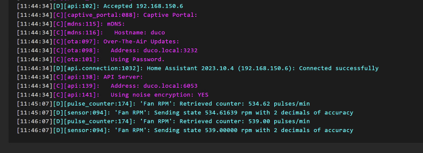
You can also check to see if it’s working in Home Assisstant:

Okay cool, it works. But it’s not very useful yet. Let’s add some controls. The first thing we need is an Output Component with a LED Controller to control the fan speed. Add the following to the configuration:
output:
  - id: duco_fan
    platform: ledc
    pin: GPIO15
    inverted: true
Next we need a Fan Component to control the fan speed and link it tot he output component we just added:
fan:
  - id: fan_motor
    name: "Fan"
    platform: speed
    output: duco_fan
Test it again by installing this configuration and you should have a fan control in Home Assistant:
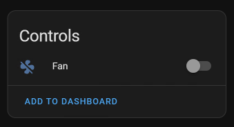
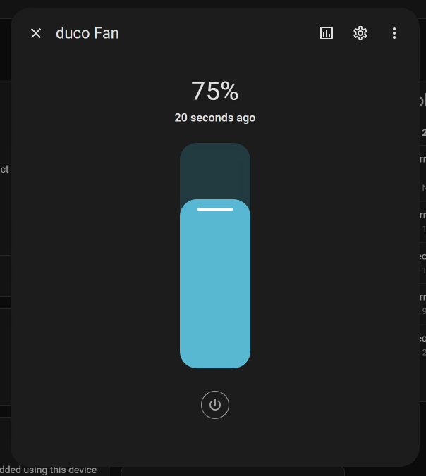
That’s it! The final config looks like this:
esphome:
  name: duco
  friendly_name: duco

esp32:
  board: esp32dev
  framework:
    type: arduino

# Enable logging
logger:

# Enable Home Assistant API
api:
  encryption:
    key: "<your-encryption-key>"

ota:
  password: "<your-password>"

wifi:
  ssid: !secret wifi_ssid
  password: !secret wifi_password

  # Enable fallback hotspot (captive portal) in case wifi connection fails
  ap:
    ssid: "Duco Fallback Hotspot"
    password: "<your-hotspot-password>"

captive_portal:

status_led:
  pin:
    number: GPIO33

sensor:
  - name: "Fan RPM"
    platform: pulse_counter
    pin: GPIO14
    unit_of_measurement: "rpm"
    accuracy_decimals: 0

output:
  - id: duco_fan
    platform: ledc
    pin: GPIO15
    inverted: true

fan:
  - id: fan_motor
    name: "Fan"
    platform: speed
    output: duco_fan
If you have no extra sensors, congratulations, you’re done! You can now control your home ventilation fan through Home Assistant. If you also want to add your sensors, keep reading.
Adding sensors
So as you read earlier, I also have the open source sensors from the Open Air project. Those sensors only need the I2C bus, but be sure to check out the software README for information about what bus to use. Lets add the I2C Component to the configuration. Since there are two ports for sensors on the board, we’ll add two I2C components:
i2c:
  - id: i2c_sensor_1
    sda: GPIO19
    scl: GPIO18
    scan: false
    frequency: 400kHz

  - id: i2c_sensor_2
    sda: GPIO16
    scl: GPIO4
    scan: false
    frequency: 400kHz
I have two sensors. A humidity and CO2 sensor connected to i2c_sensor_1, and a humidity sensor connected to i2c_sensor_2. The CO2 sensor is based on the scd4x sensor and has built-in support from ESPHome, so we can just add it to our sensor block below our fan:
sensor:
  - name: "Fan RPM"
    platform: pulse_counter
    pin: GPIO14
    unit_of_measurement: "rpm"
    accuracy_decimals: 0

  - platform: scd4x
    i2c_id: i2c_sensor_1
    co2:
      name: "Living Room CO2"
      id: living_room_co2
      accuracy_decimals: 0
    temperature:
      name: "Living Room Temperature"
      id: living_room_temperature
      accuracy_decimals: 2
    humidity:
      name: "Living Room Humidity"
      id: living_room_humidity
      accuracy_decimals: 2
    update_interval: 30s
    measurement_mode: periodic
And if all went well:
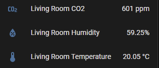
Now, the second sensor is a bit more complicated. This sensor is not supported by ESPHome out of the box. The Open AIR documentation would have you download an include file, add two libraries and add custom C++ code as a lambda to a custom sensor. This has a few downsides:
- You cannot take advantage of ESPHome’s built-in sensor options (for example selecting the i2c bus)
- You are dependant on custom C++ code that is harder to maintain
- You are dependant on external libraries that may not be maintained and are not checked by the ESPHome team
- It looks ugly in your configuration
So I took it upon myself to write a new component for ESPHome and submit it to them so everyone can use it. I have to say, that was a bit of a journey. Documentation for how to contribute to the ESPHome project are.. a bit lacking. I mean they have a guide, but it doesn’t really explain to you how a component works. The main argument in de guide (and on Discord) just seems to be “just look at other examples”. Thanks.. that really helps when debugging..
Anyway, I digress. I managed to get it working and submitted a pull request to the ESPHome project. Hopefully it will be merged soon. In the meantime, you can use my fork of ESPHome to get the component. Just add the following to your configuration:
# No longer needed when PR 5635 merges
external_components:
  - source: github://dmaasland/esphome@sht2x
    components: [sht2x]
Now you can just add the sensor to your configuration:
sensor:
  - name: "Fan RPM"
    platform: pulse_counter
    pin: GPIO14
    unit_of_measurement: "rpm"
    accuracy_decimals: 0

  - platform: scd4x
    i2c_id: i2c_sensor_1
    co2:
      name: "Living Room CO2"
      id: living_room_co2
      accuracy_decimals: 0
    temperature:
      name: "Living Room Temperature"
      id: living_room_temperature
      accuracy_decimals: 2
    humidity:
      name: "Living Room Humidity"
      id: living_room_humidity
      accuracy_decimals: 2
    update_interval: 30s
    measurement_mode: periodic

  - platform: sht2x
    i2c_id: i2c_sensor_2
    temperature:
      name: "bathroom Temperature"
      id: bathroom_temperature
    humidity:
      name: "bathroom Humidity"
      id: bathroom_humidity
And there we go:

A huge shoutout to @RobTillaart for his work on the SHT2x library. His work was invaluable in getting this component to work.
Automation
The whole part of this exercise is to gain more control over the device. However, home automation is very personal so I feel it’s better for you, the reader, to add this yourself as an exercise :). Although I do recommend checking out the disconnected mode. I’ve also implemented a variant of this in my final configuration which I’ve shared below.
Final configuration
After all is said and done, this is the configuration I’m currently running:
esphome:
  name: duco
  friendly_name: Duco MV

esp32:
  board: esp32dev
  framework:
    type: arduino

# Enable logging
logger:

# Enable Home Assistant API
api:
  encryption:
    key: "<your-encryption-key>"

ota:
  password: "<your-password>"

wifi:
  ssid: !secret wifi_ssid
  password: !secret wifi_password

  # Enable fallback hotspot (captive portal) in case wifi connection fails
  ap:
    ssid: "Duco Fallback Hotspot"
    password: "<your-hotspot-password>"

captive_portal:

i2c:
  #I2C For Sensor 1
  - id: i2c_sensor_1
    sda: GPIO19
    scl: GPIO18
    scan: false
    frequency: 400kHz
  #I2C For Sensor 2
  - id: i2c_sensor_2
    sda: GPIO16
    scl: GPIO4
    scan: false
    frequency: 400kHz

# Status led
status_led:
  pin:
    number: GPIO33

#PWM output for controlling the motor.
output:
  - platform: ledc
    pin: GPIO15
    inverted: true
    id: open_duco

fan:
  - platform: speed
    output: open_duco
    name: "Fan"
    id: fan_motor

sensor:
  # Pulse counter sensor to measure motor RPM
  - platform: pulse_counter
    pin: GPIO14
    unit_of_measurement: "RPM"
    name: "Fan RPM"

  # Sensor 1
  - platform: scd4x
    i2c_id: i2c_sensor_1
    co2:
      name: "Living Room CO2"
      id: living_room_co2
      accuracy_decimals: 0
    temperature:
      name: "Living Room Temperature"
      id: living_room_temperature
      accuracy_decimals: 2
    humidity:
      name: "Living Room Humidity"
      id: living_room_humidity
      accuracy_decimals: 2
    update_interval: 30s
    measurement_mode: periodic

  # Sensor 2
  - platform: sht2x
    i2c_id: i2c_sensor_2
    temperature:
      name: "bathroom Temperature"
      id: bathroom_temperature
      accuracy_decimals: 2
    humidity:
      name: "bathroom Humidity"
      id: bathroom_humidity
      accuracy_decimals: 2

globals:
  # Disconnected Mode Max Fan Speed, linked to Disconnected Hum Level Max Speed
  - id: disconnected_max_fan_speed
    type: int
    restore_value: no
    initial_value: "100"
  # Disconnected Mode Medium Fan Speed, linked to Disconnected Hum Level Medium Speed
  - id: disconnected_medium_fan_speed
    type: int
    restore_value: no
    initial_value: "60"
  # Disconnected Mode Default Fan Speed, for humidities lower than Disconnected Hum Level Medium Speed
  # or if NOT using a humidity sensor. Without sensor this speed will be maintained untill a connection
  # to Home Assistant has been restored and your automations can take over.
  - id: disconnected_default_fan_speed
    type: int
    restore_value: no
    initial_value: "25"
  # Disconnected Mode Max Fan Speed Threshold
  - id: disconnected_hum_level_max_speed
    type: int
    restore_value: no
    initial_value: "75"
  # Disconnected Mode Medium Fan Speed Threshold
  - id: disconnected_hum_level_medium_speed
    type: int
    restore_value: no
    initial_value: "55"

script:
  - id: disconnected_mode
    mode: single
    then:
      - logger.log: "Disconnected Mode Triggered"
      - fan.turn_on:
          id: fan_motor
          speed: !lambda |-
            auto hum = id(air_humidity).state;

            if (hum >= id(disconnected_hum_level_max_speed)) {
              return id(disconnected_max_fan_speed);
            }

            if (hum >= id(disconnected_hum_level_medium_speed)) {
              return id(disconnected_medium_fan_speed);
            }

            return id(disconnected_default_fan_speed);

interval:
  - interval: 30s
    then:
      - logger.log: "API Connectivity Check for Disconnected Mode"
      - if:
          condition:
            not:
              api.connected:
          then:
            - logger.log: "API disconnected"
            - script.execute: disconnected_mode
          else:
            - logger.log: "API connected"
            - script.stop: disconnected_mode

external_components:
  - source: github://dmaasland/esphome@sht2x
    components: [sht2x]
That’s it! I hope you enjoyed this write-up and found it useful. If you have any questions, feel free to reach out to me on Twitter.
